WIRE ROPE ROTATIONAL PROPERTIES
Rotation-resistant wire ropes are ropes that are designed such that they create a reduced torque and a reduced rotation under load. In general, they are composed of a construction of at least two strand layers that are helically stranded around a core. The outer strand layers in this construction are stranded opposite to the strand layer below.

ROTATION-RESISTANT A
The rotational property is less than or equal to 1 rotation/1,000 d, when a load corresponding to 20% of the minimum breaking force is lifted; a swivel may be used.
ROTATION-RESISTANT B
The rotational property is greater than 1 rotation but less than 4 rotations/1,000 d, when a load corresponding to 20% of the minimum breaking force is lifted; a swivel may be used in accordance with the recommendations of the rope manufacturer and/or with the approval of a competent person.
NOT ROTATION-RESISTANT
The rotational property is greater than 4 rotations/1,000 d under a load corresponding to 20% of the minimum breaking force; a swivel should not be used.
1 rotation = 360°
d = rope diameter
Fmin = minimum breaking force of the rope
Rotation Resistant Wire Rope
Rotation resistant wire rope is a special category (class) of wire rope designed to resist the tendency to spin or rotate under load. In general these ropes are used as single part lines, or in situations where operating conditions require a rope that will resist cabling in a multipart system. The essential nature of rotation resistant rope designs impose certain limitations on their application and necessitate special handling requirements not encountered with other rope constructions.
Rotation resistant wire rope is available in two general classifications:
1) Single layer-consisting of a single layer of three or four strands. Typically the strands support one another without a core member.
2) Multilayer strand (Multistrand)-consisting of two or more strand layers closed in opposing directions. Torsional forces generated by each layer of the rope counteract one another to minimize rotation.
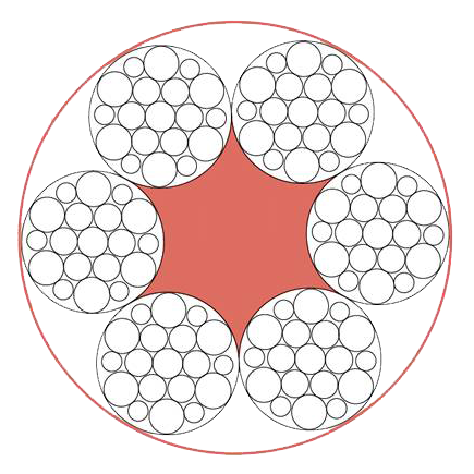
The multistrand classification includes ropes with between eight and twenty outer strands. Table 1 of this manual describes some of the more commonly available rotation resistant multistrand rope classification. In addition to these, a wide variety of special multistrand ropes is available. See (Figure 9). It would be impractical to cover the specific features of each in this manual.
Figure 9. Cross sections of rotation resistant rope constructions.
In multistrand rotation resistant ropes the crossover points between strand layers are points of high stress concentration. Relative motion of the strands at these points results in accelerated deterioration of the internal components of the rope. Because of this design characteristic of the multistrand construction, care must be taken to avoid high loads with small diameter sheaves. Design factors less than five are not recommended.

For assistance in rope selection we recommend contacting our Technical Department to ensure the proper wire rope for your application.
Figure 10. Relative rotation with one end allowed to rotate freely.
Special Recommendations For Rotation Resistant Ropes
Many rotation resistant ropes are partially preformed. Ends of the rope should be seized tightly, welded or brazed, to prevent lay disturbances of the outer strands or core (two seizings are recommended). Care must be taken to avoid inducing twist into the rope during handling and installation.
Guidelines for the installation of rotation resistant rope:
- Follow instructions for removing rope from a reel or coil. See page 26 Figure 19 – 21.
- Use a pulling grip fitted with a swivel when pulling new rope through the reeving system with a used rope. This practice will prevent residual twist in the pulling rope from being transferred to the new rope. The pulling rope should be the same-lay direction as the new rope.
- Back tension should be applied to the payoff reel of the new rope to insure a tight even spooling on the drum.
- Operate the new rope through several complete cycles at light load. This will allow the rope to adjust gradually to operating conditions.


No comment